Indirect Command Buffer은 인코딩된 GPU 명령들을 지속적으로 저장하기에, 이를 활용하면 명령을 한 번 인코딩하고 여러 번 재사용할 수 있습니다. CPU의 여러 스레드와 GPU의 컴퓨팅 커널을 사용하여 명령을 Indirect Command Buffer로 동시에 인코딩할 수도 있습니다. 즉, 다음과 같이 시작할 때 모델을 불러오고 나서, 이후에 렌더 패스를 생성하고 해당하는 명령을 생성하여 집어 넣는 식으로 drawing 작업이 수행되었습니다.
렌더 패스 당 명령을 생성하는 것 대신, 명령들의 리스트를 포함한 indirect command buffer를 생성하여 명령을 관련된 자원들 및 그리는 방법을 설정하고, 렌더 루프 동안, 이를 실행시켜 인코더가 한번의 명령으로 명령의 집합을 실행할 수 있도록 합니다.
명령을 하나씩 하나씩 실행시킨 경우, CPU와 GPU 사이의 데이터 전송이 발생하여 이에 의한 정지 및 오버헤드가 발생합니다.
indirect command를 사용한다면, CPU는 한번에 다수의 명령을 인코딩하여, GPU가 모든 패스를 수행한 뒤 CPU로 돌아오게 됩니다.
이를 위해서는 다음과 같은 순서로 작업이 수행되어야 합니다.
버퍼에 uniform 데이터를 전부 배치 시킵니다. indirect command는 프로그램이 시작될 때 buffer를 가리키고 있어, GPU에 임시 바이트를 보낼 수 없습니다.
위의 과정이 CPU에서 수행하는 과정으로 command list를 설정하고 이를 렌더링 하였습니다. 하지만 이는 GPU에서 더 나은 방식으로 수행 가능합니다. CPU에서는 for문을 이용하여 순차적으로 사용하였지만, GPU에서는 병렬적으로 수행 가능합니다. 프로그램이 시작한 직후 render loop를 설정하는 것은 보이지 않는 물체도 렌더링하는 등의 비효율적인 부분이 많습니다. 따라서 command list를 상황에 맞게 유동적으로 GPU에서 빠르게 생성한다면 더 효과적으로 운용가능합니다.
이전까지는 복잡한 모델의 텍스처와 질감 등 여러 요소들을 각자 따로 CPU에서 GPU로 할당하는 작업을 수행하였습니다. 이는 CPU 오버헤드를 유발하여 자원을 낭비하기 때문에, 이를 한번에 수행하기 위하여 argument buffer를 도입하였습니다. 이는 texture, sampler, buffer과 같이 렌더링에 있어 필수불가결하지만 비싼 작업들이 반복적으로 수행되어야 하는데, 이를 argument buffer로 감싸 한번에 설정하는 것이 가능해집니다.
이전에 argument buffer로 자원에 접근하는 방법을 배웠다면 이번에는 자원들의 배열과 자원 heap을 argument buffer과 함꼐 사용하는 방법을 배워보겠습니다. 특히 배열을 포함하는 argument buffer 구조체를 어떻게 정의하고 heap에서 자원을 어떻게 할당하고 사용하는 지에 집중하도록 하겠습니다. 그 후에 argument buffer 내의 자원을 그래픽 및 연산 함수에서 어떻게 인코딩 하는지 배우고 이를 어떻게 쓰고 읽는 지에 대해서 배워나가겠습니다.
Define argument buffers
MSL에서는 argument buffer를 사용자 지정 구조로 정의할 수 있어, 다음과 같이 결정할 수 있습니다. 밑의 예시는 metal3의 기준을 따랐습니다.
Metal은 GPU가 접근하는 메모리를 효율적으로 관리하기에, 어떠한 접근 레벨을 가졌는 지 사전에 확인을 합니다. 이는 이전 RenderCommandEncoder에서 이를 자원별로 관리를 하였지만, argument buffer에서는 자원을 개별적으로 관리할 수 없고, 이를 부분적으로 개별 검사하는 것은 성능 상의 이점을 상쇄시킵니다. 따라서, 접근할 때 RenderCommandEncoder에서 특정 메모리의 접근에 대한 지침을 미리 설정하여 이를 활용하게 됩니다.
Arrays of Arguments in the Metal Shading Language
배열은 그래픽 및 연산 함수의 매개 변수로 사용될 수 있는데, 함수가 배열을 매개 변수로서 사용할 때, 첫 번째 리소스의 인덱스는 배열 매개 변수 자체의 기본 인덱스와 같습니다. 따라서, 배열의 각 후속 리소스에는 기본 인덱스 값에서 추가하여 후속 인덱스 값이 자동으로 할당됩니다.
fragment float4 exampleFragmentFunction(array<texture2d<float>, 10> textureParameters [[ texture(5) ]])
예를 들어, 다음 조각 함수인 exampleFragmentFunction에는 기본 인덱스 값이 5인 텍스처 배열인 textureParameters라는 매개 변수가 있습니다. textureParameters에는 [[ texture(5) ]] 속성 한정자가 있기 때문에 이 매개 변수를 설정하는 해당 Metal 프레임워크 메서드는 setFragmentTexture:atIndex:이며 여기서 인덱스 값은 5로 시작합니다. 따라서 배열 인덱스 0의 텍스처는 인덱스 번호 5로, 배열 인덱스 1의 텍스처는 인덱스 번호 6으로 설정된다. 배열의 마지막 텍스처인 배열 인덱스 9는 인덱스 번호 14로 설정됩니다.
Define Argument Buffers with Arrays
argument buffer 구조의 요소로 배열이 사용될 수 있으며, 이 경우 배열의 기본 인덱스 값 n을 가지는 argument buffer의 [[ id(n) ]] 속성 한정자는 함수 매개변수의 [[ texture(n) ]] 속성 한정자와 동일한 방식으로 동작합니다. 그러나 MTLenderCommandEncoder 개체에서 setFragmentTexture 메서드를 보다는 MTLArgumentEncoder 개체에서 setTexture를 통해 배열에서 argument buffer로 텍스처로 인코딩합니다. argument buffer의 구조는 다음과 같이 정의 가능합니다.
지금까지 사용한 텍스처와 버퍼는 배열에 같이 존재하지만 자원에 대한 접근을 할때 개별적으로 검증하였습니다. 이를 해결하기 위해서 MTLHeap 개체에 자원을 할당하고, 이를 createHeap 메서드를 한번만 호출하여 힙의 전체 자원을 GPU에서 접근할 수 있도록 하였습니다. 이는 아래의 loadResources 메서드에서 구현됩니다. 또한, moveResourcesToHeap 메서드를 통해 영구적인 MTLTexture과 MTLBuffer 객체를 힙에 할당하고, MTLBlitCommandEncoder를 사용하여 자원 데이터를 임시 객체에서 영구 객체로 복사합니다.
void createHeap()
{
    MTLHeapDescriptor *heapDescriptor = MTL::HeapDescriptor::alloc()->init();
    heapDescriptor->setStorageMode(MTL::StorageMode::StorageModePrivate);
    heapDescriptor->setSize(0);

    // Build a descriptor for each texture and calculate the size required to store all textures in the heap
    for(uint32_t i = 0; i < AAPLNumTextureArguments; i++)
    {
        // Create a descriptor using the texture's properties
        MTL::TextureDescriptor* texture2DDescriptor(_texture[i]->pixelFormat(), _texture[i]->width(), _texture[i]->height(), _texture[i]->mipmapLevelCount ? true : false);

        // Determine the size required for the heap for the given descriptor
        MTL::SizeAndAlign sizeAndAlign = MTL::heapTextureSizeAndAlign(descriptor);

        // Align the size so that more resources will fit in the heap after this texture
        sizeAndAlign.size += (sizeAndAlign.size & (sizeAndAlign.align - 1)) + sizeAndAlign.align;

        // Accumulate the size required to store this texture in the heap
        heapDescriptor->setSize(heapDescriptor->Size() + sizeAndAlign.size);
    }

    // Calculate the size required to store all buffers in the heap
    for(uint32_t i = 0; i < AAPLNumBufferArguments; i++)
    {
        // Determine the size required for the heap for the given buffer size
        MTL::SizeAndAlign sizeAndAlign = MTL::heapBufferSizeAndAlign(_dataBuffer[i]->length(), MTL::ResourceStorageModePrivate);

        // Align the size so that more resources will fit in the heap after this buffer
        sizeAndAlign.size +=  (sizeAndAlign.size & (sizeAndAlign.align - 1)) + sizeAndAlign.align;

        // Accumulate the size required to store this buffer in the heap
        heapDescriptor->setSize(heapDescriptor->Size() + sizeAndAlign.size);
    }

    // Create a heap large enough to store all resources
    _heap = _device->newHeap(heapDescriptor);
}


void moveResourcesToHeap()
{
    // Create a command buffer and blit encoder to copy data from the existing resources to
    // the new resources created from the heap
    id <MTLCommandBuffer> commandBuffer = [_commandQueue commandBuffer];
    commandBuffer.label = @"Heap Copy Command Buffer";

    id <MTLBlitCommandEncoder> blitEncoder = commandBuffer.blitCommandEncoder;
    blitEncoder.label = @"Heap Transfer Blit Encoder";

    // Create new textures from the heap and copy the contents of the existing textures to
    // the new textures
    for(uint32_t i = 0; i < AAPLNumTextureArguments; i++)
    {
        // Create a descriptor using the texture's properties
        MTLTextureDescriptor *descriptor = [AAPLRenderer newDescriptorFromTexture:_texture[i]
                                                                      storageMode:_heap.storageMode];

        // Create a texture from the heap
        id<MTLTexture> heapTexture = [_heap newTextureWithDescriptor:descriptor];

        heapTexture.label = _texture[i].label;

        [blitEncoder pushDebugGroup:[NSString stringWithFormat:@"%@ Blits", heapTexture.label]];

        // Blit every slice of every level from the existing texture to the new texture
        MTLRegion region = MTLRegionMake2D(0, 0, _texture[i].width, _texture[i].height);
        for(NSUInteger level = 0; level < _texture[i].mipmapLevelCount;  level++)
        {

            [blitEncoder pushDebugGroup:[NSString stringWithFormat:@"Level %lu Blit", level]];

            for(NSUInteger slice = 0; slice < _texture[i].arrayLength; slice++)
            {
                [blitEncoder copyFromTexture:_texture[i]
                                 sourceSlice:slice
                                 sourceLevel:level
                                sourceOrigin:region.origin
                                  sourceSize:region.size
                                   toTexture:heapTexture
                            destinationSlice:slice
                            destinationLevel:level
                           destinationOrigin:region.origin];
            }
            region.size.width /= 2;
            region.size.height /= 2;
            if(region.size.width == 0) region.size.width = 1;
            if(region.size.height == 0) region.size.height = 1;

            [blitEncoder popDebugGroup];
        }

        [blitEncoder popDebugGroup];

        // Replace the existing texture with the new texture
        _texture[i] = heapTexture;
    }

    // Create new buffers from the heap and copy the contents of existing buffers to the
    // new buffers
    for(uint32_t i = 0; i < AAPLNumBufferArguments; i++)
    {
        // Create a buffer from the heap
        id<MTLBuffer> heapBuffer = [_heap newBufferWithLength:_dataBuffer[i].length
                                                      options:MTLResourceStorageModePrivate];

        heapBuffer.label = _dataBuffer[i].label;

        // Blit contents of the original buffer to the new buffer
        [blitEncoder copyFromBuffer:_dataBuffer[i]
                       sourceOffset:0
                           toBuffer:heapBuffer
                  destinationOffset:0
                               size:heapBuffer.length];

        // Replace the existing buffer with the new buffer
        _dataBuffer[i] = heapBuffer;
    }

    [blitEncoder endEncoding];
    [commandBuffer commit];
}
Encode Data into Argument Buffers
먼저 초기화하는 동안 CPU에서 argument buffer은 다음과 같이 정의가 됩니다.
tessellation에서는 주어진 mesh에서 더 많은 삼각형으로 쪼개는 작업을 수행합니다. 이를 통해, 메모리와 대역폭에서 장점을 갖습니다. 또한, GPU에 더 적은 데이터를 보내는 것이 가능해집니다. GPU가 tessellated된 정점을 그래픽 메모리에 저장하지 않기 때문에 자원에서 더 큰 효율을 얻을 수 있습니다. 굴곡에서 더 많은 정점과 삼각형을 생성하기에 더 부드럽게 만들 수도 있으며, 카메라 위치에 따른 정밀도를 다르게 설정할 수 있습니다.
Tessellation and Terrain
3D mesh가 너무나 커서 메모리 제한으로 인해 이를 모두 렌더링하지 못하는 경우가 존재합니다. 예를 들면 눈 위의 발자국이 그러한 예입니다. 이를 해결하기 위한 방법 중 하나로 세세한 표면 법선을 저장하는 텍스처 맵을 생성하여 mesh의 Geometry를 줄일 수 있습니다. 이를 normal mapping이라고 합니다. 이는 실루엣 가장자리는 매쉬로서 이용하지 않아, 항상 올바른 결과를 내지는 않지만 정점 수를 줄일 수 있습니다.
또 다른 방법으로는, 인스턴스화 기법으로 동일한 mesh를 사용하는 경우 복제하지 않고 여러 번 그리는 방법입니다. 이는 잔해, 나뭇잎 또는 군중을 표현할 때 유효하게 사용될 수 있습니다.
Tessellation은 geometry를 추가적인 메모리를 할당할 필요 없이 정점을 고정할 수 있습니다. geometry가 세분화된 후에는 displacement mapping과 같은 기술을 사용하여 지정된 정점의 위칠르 조정하여 긴 실루엣 모서리를 포함하여 표면에 대해 좀 더 자세한 정보를 만들 수 있습니다.
Patches
Metal은 삼각형과 사각형 형태의 두 패치 타입을 가집니다. tessellation은 결과적으로 항상 삼각형들을 생성하지만, 기본 geometry는 선택 가능합니다. tessellation을 위한 mesh를 선택할 때 기본 파이프라인이 자동적으로 패치 geometry를 삼각화하지 않는 것이 중요합니다. 사각형은 현대 그래픽 API에서 기본 primitive를 잘 사용되지 않아, 몇몇 포맷에서는 인코딩되지 않습니다.
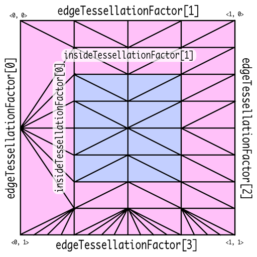
Tessellation Factors
Tessellation Factor는 patch domain에서 얼마나 잘라야하는 지를 명시합니다. 삼각형의 경우는 세 변이 어떻게 변하는 지를 명시하는 edgeTessellationFactor과 내부 지역에서는 몇개로 나뉘는 지를 명시하는 insideTessellationFactor를 필요로 합니다. 사각형의 경우는 네 변에 대한 edgeTessellationFactor과 내부에 대해서는 두 개의 insideTessellationFactor를 필요로 합니다.
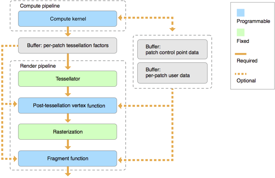
Metal Tessellator Pipeline
tessellation은 제어점의 집합으로 정의된 geometry의 임의의 배열인 patch 단위에 대해서 동작 합니다. 각 패치별 tessellation factor, 사용자 데이터 및 patch 제어점 데이터는 각각 별도의 MTL::Buffer 개체에 저장됩니다.
[Compute Kernel(Tessellation Kernel)]
Tessellation은 먼저 위의 Tessellation Factor를 결정하는 것부터 시작합니다. 이는 연산 셰이더를 통해 수행될 수 있지만 필수적이지는 않습니다. 이를 통해 패치 당 얼마나 나뉘어져야하는지를 결정하고, 패치 당 데이터 및 제어점을 연산, 변경합니다. 이는 hull shader와 유사한 역할을 수행합니다. 다음과 같은 코드의 형태를 띕니다
kernel void my_compute_kernel(...) {...}
[Tessellator]
Tessellation Factor는 고정 함수인 tessellaotr 단계에서 Geometry를 세분화하고 이를 vertex shader로 전송하는데 사용됩니다. Hardware Tessellator에 해당합니다. 이는 다른 그래픽 API의 tessellator와 유사합니다
[Post-Tessellation Vertex Shader]
Post-tessellation vertex Shader는 일반적인 vertex shader와 유사하지만, 패치 도메인 내의 정점 속성과 좌표에 대해서만 동작합니다. 이는 domain-shader와 유사한 역할을 수행합니다.
post-tessellation vertex function은 buffer, texture 혹은 샘플러를 자원으로 받고, [[stage_in]] 한정자를 선언하거나 버퍼에서 직접적으로 읽어 패치별 데이터나 패치 제어점 데이터를 사용할 수 있습니다. [[patch_id]]는 패치 식별자를, [[instance_id]]는 기본 개체값을 포함한 개체별 식별자를, [[base_instance]]는 기본 인스턴스 값을, [[position_in_patch]]는 평가되는 위치를 결정하는 값을 표기합니다.
Patch Draw Calls
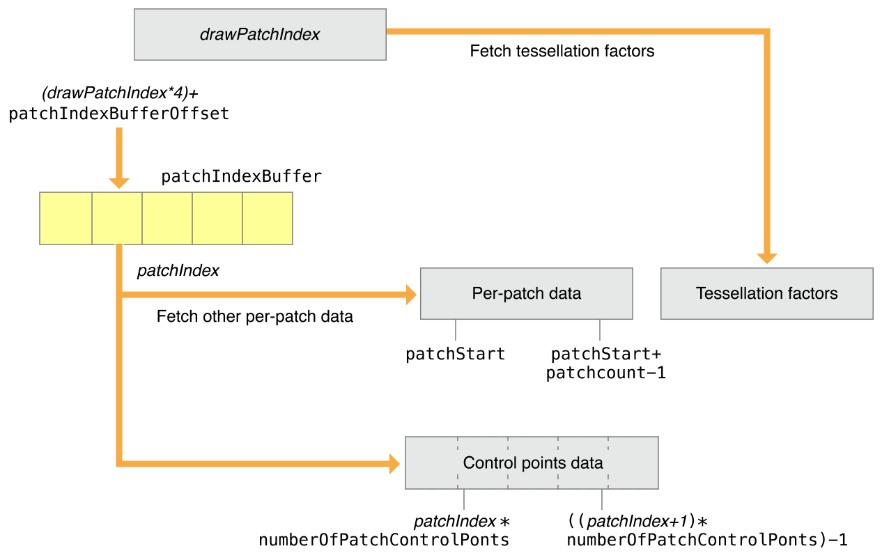
모든 patch draw call은 baseInstance 인자로 지정된 값부터 시작하여 연속 배열 요소로 패치별 데이터와 패치 제어점 배열이 구성됩니다. 패치 데이터를 렌더링하기 위해서는 patch draw는 패치별 데이터와 패치 제어점 데이터를 가지고 있는데, 패치 데이터는 하나 이상의 버퍼에서 하나 이상의 매시의 모든 패치를 동시에 저장하고 있습니다. 연산 커널은 장면 의존적인 패치별 tessellation factor를 생성하기 위하여 실행됩니다. 연산 커널은 폐기되지 않는 패치에 대해서만 인자를 생성할 수 있습니다. 따라서 patch index 버퍼는 그릴 패치의 패치 ID를 식별하는데 사용됩니다.
[patchStart, patchStart+patchCount-1] 범위의 버퍼 인덱스(drawPatchIndex)는 데이터를 참조하는 데 사용됩니다. 패치별 데이터와 패치 제어 지점 데이터를 가져오는 데 사용되는 패치 인덱스가 연속되지 않은 경우 drawPatchIndex는 아래와 같이 patchIndexBuffer를 참조할 수 있습니다.
patchIndexBuffer의 각 요소에는 패치별 데이터와 패치 제어점 데이터를 참조하는 32비트 patchIndex 값이 포함되어 있습니다. patchIndexBuffer에서 가져온 patchIndex는 (drawPatchIndex*4) + patchIndexBufferOffset 위치에 있습니다. 패치의 제어점 지수는 다음과 같이 계산됩니다.
또한 patchIndexBuffer는 패치별 데이터 및 패치 제어 지점 데이터를 읽는 데 사용되는 patchIndex가 패치별 테셀레이션 계수를 읽는 데 사용되는 인덱스와 다를 수 있도록 지원합니다. 테셀레이터의 경우 drawPatchIndex는 패치별 테셀레이션 요인을 가져오는 인덱스로 직접 사용됩니다. patchIndexBuffer가 NULL인 경우 drawPatchIndex와 patchIndex는 동일한 값을 가집니다.
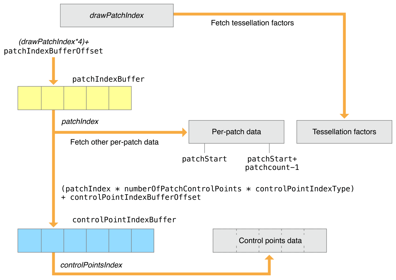
제어점이 패치 간에 공유되거나 패치 제어점 데이터가 연속되지 않은 경우 drawIndexedPatches 방법을 사용해야 합니다. patchIndex는 지정된 controlPointIndexBuffer를 참조합니다. 이 버퍼에는 패치의 제어점 인덱스가 들어 있습니다. (tessellationControlPointIndexType은 controlPointIndexBuffer의 제어점 인덱스의 크기가 설명되며 uint16 혹은 uint32 형태이어야만 합니다).
controlPointIndexBuffer에서 첫 번째 제어점 색인의 위치는 controlPointIndexBufferOffset + (patchIndex * numberOfPatchControlPoints * controlPointIndexType == UInt16 ? 2 : 4)과 같이 연산됩니다. 여러 제어점 색인은 첫 제어점 색인의 위치부터 시작하여 controlPointIndexBuffer에 연속적으로 저장되어야만 합니다.
RenderPipelineDescriptor를 생성하는 것은 동일하지만, tessellation에 대해 설명을 부여해야 합니다. Metal에서 attribute buffer에서 자동적으로 제어점 데이터를 가져오는 것을 요청하기에, 버퍼 레이아웃의 StepFunction을 사용하여 정점 단위가 아닌 제어점 단위 데이터를 가져옵니다.
tessellationFactorStepFunction은 새로운 factor을 어마나 자주 tessellation factor buffer에서 가져오는 지를 결정합니다. 여기서 constant는 모두 같은 factor를 사용한다는 뜻입니다.
tessellationControlPointIndexType은 제어점에 인덱싱되었을 때 가져오는 값에 관련되어 있습니다.
GPU를 이용하여 GPU 내에서 텍스처를 생성하고 이를 활용해보겠습니다. 이를 위해 GPU 내에 텍스처를 사용하기 위한 공간을 만들어 주고, 이를 access::write를 매개변수로 하는 텍스처를 받아들이고 write 함수를 통해 위치에 맞는 색상을 그릴 수 있도록 합니다. 이 때, gridSize 및 index를 사용하여 텍스처의 위치를 결정짓습니다.
kernel void mandelbrot_set(texture2d< half, access::write > tex [[texture(0)]],
                           uint2 index [[thread_position_in_grid]],
                           uint2 gridSize [[threads_per_grid]])
{
    // Scale
    float x0 = 2.0 * index.x / gridSize.x - 1.5;
    float y0 = 2.0 * index.y / gridSize.y - 1.0;

    // Implement Mandelbrot set
    float x = 0.0;
    float y = 0.0;
    uint iteration = 0;
    uint max_iteration = 1000;
    float xtmp = 0.0;
    while(x * x + y * y <= 4 && iteration < max_iteration)
    {
        xtmp = x * x - y * y + x0;
        y = 2 * x * y + y0;
        x = xtmp;
        iteration += 1;
    }

    // Convert iteration result to colors
    half color = (0.5 + 0.5 * cos(3.0 + iteration * 0.15));
    tex.write(half4(color, color, color, 1.0), index, 0);
}
연산 파이프라인은 렌더링 파이프라인보다 좀 더 간단한 편인데, 이는 단일 기능만을 포함하고 다른 상태 집합을 포함하지 않아도 되기 때문입니다. 이전에는 replaceRegion으로 메모리를 채웠다면, 이번에는 텍스처를 GPU 연산을 통해서 채워야 합니다. 따라서 다음과 같은 인코딩을 통해 파이프랑니을 설정하고 dispatchThreads() 메서드를 통해 커널을 실행합니다.
렌더러는 이미지 데이터로 이 메모리를 채워야 합니다. 일반적으로 프로그램은 이미지 파일의 데이터로 메모리를 채우지만, Metal에서는 이를 위한 API를 제공하지 않으므로, MetalKit 또는 Image I/O와 같은 다른 라이브로리를 통해 수행해야 합니다. 이번에는 임시 시스템 메모리 버퍼를 alloca를 통해 할당한 후 체크 이미지를 생성하여 사용합니다.
파이프라인이 삼각형을 처리하기 fragment 단계로 넘어갈 때, depthCompareFunction의 속성을 이용하여 거리를 재어, 이를 사용할 지 제거할 지를 결정합니다. CompareFunctionLess로 설정하면 렌더러는 더 가까운 경우만 남깁니다. depthWrite를 활성화하면 파이프라인은 향후 비교를 위해 픽셀의 깊이 값을 업데이트합니다.
간략하게 소개를 하자면, 동일한 mesh를 공유하는 여러 물체를 그릴 때, 하나씩 draw를 호출하여 그리는 것보다 한번의 draw에 동일한 물체들을 한번에 다 그리는 것이 더 효율적입니다. 렌더러는 각 개체에 대한 위치 및 색을 따로 보관하고, 이를 적용하여 그릴 수 있습니다. 먼저 instancedatabuff부터 만들어, 각 개체가 가진 고유한 특성을 저장하게 해야합니다.
for ( size_t i = 0; i < kMaxFramesInFlight; ++i )
{
    _pInstanceDataBuffer[ i ] = _pDevice->newBuffer( instanceDataSize, MTL::ResourceStorageModeManaged );
}
그 후에, 필요한 데이터를 _pInstanceDataBuffer에 적절하게 채워넣어 줍니다. 그 후에 이를 setVertexBuffer로 등록을 하고, draw 함수를 호출할 때 drawIndexedPrimitives를 호출하여, indexbuffer가 사용한 draw 함수를 호출해야 합니다.
렌더 패스는 텍스처 집합을 그리는 렌더링 명령의 집합입니다. 샘플 코드를 살펴가면서 이를 살펴볼 것인데, 먼저 첫 번째 패스는 텍스처에 이미지를 그려넣기 위하여 사용자 지정 Renderpass를 구성할 것이며 이는 일반적인 텍스처가 아닌 만들어지기에 offscreen render pass라 합니다. 두 번째는 MTKView 개체가 제공하는 RenderpassDescriptor를 사용하여 최종 이미지를 렌더링하고 표시합니다. 이때 텍스처는 offscreen render pass의 결과물을 사용합니다. offscreen render pass는 더 크고 복잡한 렌더러를 구성하기 위한 기본 구성 요소로 사용됩니다.
Create a Texture for the Offscreen Render Pass
MTKView 객체는 렌더링할 그리기 가능한 텍스처를 자동으로 생성하며, 이번에는 offscreen render pass를 수행하는 동안 그려낼 텍스처도 필요로 합니다.이러한 텍스처를 위하여 먼저 MTL::TextureDescriptor 개체를 만들고 속성을 구성합니다.
여기서 usage는 새로운 텍스처를 어떻게 사용할 지를 의미하며, 이는 텍스처에 이미지가 쓰여지고 나서 읽히는 과정을 거치기 때문에, RenderTarget과 ShaderRead 플래그를 사용하였습니다. 이는 용도에 맞는 텍스처만을 구성하여 성능을 향상시킵니다. 그리고 TextureDescriptor로 설정한 Texture를 실제로 _renderTargetTexture로 만들어내고 TextureDescriptor 객체는 메모리 해제시킵니다.
Create the Render Pipelines
렌더 파이프라인은 실행할 vertex function 및 fragment function을 포함한 drawing 명령을 어떻게 실행시키며 이들의 픽셀 포맷은 어떠한 지를 결정합니다. 아래의 코드는 offscreen render 파이프라인에 사용될 render pass를 만듭니다.
여기서 load action은 GPU가 drawing 명령을 수행하기 전에 렌더 패스가 시작될 떄 텍스처의 초기 내용을 결정하며, 마찬가지로 store action은 최종 이미지를 텍스처에 다시 덮어씌울지의 여부를 결정합니다. 위의 경우는 샘플로 렌더링 대상의 내용을 지우는 load action과 렌더링된 데이터를 텍스처에 다시 저장하는 store action을 취합니다. 이는 결과값을 텍스처에 저장하여 다음 render pass가 사용할 수 있도록 합니다.
Metal은 다음과 같은 load 및 store 작업을 사용하여 GPU가 텍스처 데이터를 관리하는 방법을 최적화합니다. 큰 텍스처의 경우 많은 메모리를 소모하며 이를 전송하기 위해서는 큰 메모리 대역이 소모됩니다. 렌더 대상의 동작을 적절하게 설정하는 것으로 GPU가 텍스처에 접근할 때 사용하는 메모리 대역폭의 양을 줄일 수 있어, 성능과 배터리 수명을 향상시킬 수 있습니다.
LoadAction과 StoreAction에 대해서 조금만 더 자세히 짚고 넘어가도록 하겠습니다. 위와 같이 texture에 대해서 속성을 정의할 수 있는데, 먼저 LoadAction에는 3가지 옵션이 존재합니다.
dontCare - 렌더 대상의 이전 데이터가 필요 없고 모든 픽셀에 대해서 작업을 수행할 때 사용될 수 있습니다. 이 작업은 비용이 들지 않으며, 픽셀 값은 초기에 미정의 상태로 시작합니다
clear - 이전의 값은 필요 없지만 픽셀 전체가 아닌 일부에 대해서만 작업을 수행할 때 사용될 수 있으며, 각 픽셀에 값을 새로 써넣는 비용이 발생합니다.
load - 이전의 렌더 대상의 내용이 필요하거나 일부의 픽셀만을 재렌더링이 필요한 경우 사용될 수 있습니다. 이는 각각의 픽셀에 대해 메모리에서 읽어오는 비용이 발생하기에, 위의 두 옵션보다는 속도가 느립니다.
StoreAction에는 4가지 옵션이 존재합니다. 이때 보통 렌더 대상이 멀티샘플링된 텍스처로 존재하는데, 이를 멀티 샘플된 형태를 취할 것인지 아니면 따로 처리할 것인지(resolved data)
dontCare - 렌더 대상을 저장할 필요 없는 경우 사용될 수 있습니다. 이 작업은 비용이 들지 않으며, 픽셀 값은 초기에 미정의 상태로 시작합니다. 이는 보통 depth나 stencil에 대해서 수행합니다.
store - 렌더 대상을 저장할 필요가 있을 때 사용됩니다. 이는 저장하는 비용이 발생하는데, 렌더 대상이 다시 사용될 떄 수행됩니다.
multisampleResolve - GPU가 멀티 샘플링된 데이터를 픽셀 당 하나의 샘플로 분해하고 분해된 텍스처에 데이터를 저장합니다. 나중에 버려지게 됩니다. 이는 렌더 패스 끝의 멀티 샘플링 내용은 확인해야 하지만, 이는 추후에 버려지기 떄문에 저장할 필요가 없는 경우에 사용됩니다.
storeAndmultisampleResolve- store과 multisampleResolve를 모두 수행합니다.
이떄 store을 수행하는 두 옵션의 경우 memoryless한 렌더 대상에 대해서는 수행 불가능 합니다. 여기서의 memorylesss는 GPU 내의 tile memory와 같이 일시적으로 생겨났다가 CPU로 되돌아가지 않고서 사라지는 메모리를 의미하며, ResourceStorageMode 중 하나로, 나머지인 public은 CPU와 GPU 둘 다에서 모두 접근 가능하고, private은 GPU에서만 접근 가능한 경우를 얘기합니다. 또한 이러한 store 옵션은 뒤로 늦출 수 있는데 unknown으로 설정하면 됩니다. 이는 다른 옵션을 조기에 저장하는 것으로 인한 잠재적인 비용을 피할 수 있지만, render pass 인코딩을 완료하기 전에 올바른 저장 작업을 지정하지 않으면 오류가 발생할 수 있습니다.
Render to the Offscreen Texture
render pass를 인코딩하기 전에 Metal이 어떻게 GPU 상의 명령을 스케쥴링하는 지를 이해할 필요가 있습니다. 프로그램이 명령 대기열에 명령 버퍼를 넘기면 Metal은 명령을 순차적으로 실행하는 것처럼 행동해야 합니다. 하지만 높은 성능과 GPU 활용도를 위해서는, Metal은 순차적으로 수행하는 것과 다른 결과를 내지 않는 한도 내에서 동시적으로 명령을 실행시킵니다. 이를 사전에 공지하기 위해, render pass가 자원에 적혀 이를 같이 읽어내어 Metal이 종속성을 확인하게 됩니다. 이번 코드의 경우는 첫번째 render pass가 종료되기 전까지 두 번째 render pass의 실행을 자동적으로 지연시킵니다. 따라서, CPU와 GPU 작업을 명시적으로 동기화하는 것과 같은 특별한 작업은 필요로 되지 않으며, 단순히 두 개의 패스를 순차적으로 인코딩하고, 이를 수행하도록 만듭니다. 이를 위해서 두 render pass를 하나의 command buffer로 순서에 맞게 인코딩하면됩니다. 먼저, 이전에 만든 offscreen render pass descriptor를 사용하여 render command encoder를 생성합니다.
이후의 작업은 일반적인 렌더링 작업과 동일합니다. metal-cpp 1을 참조하면 됩니다. 이후에 endEncoding()을 명시해주어 끝을 알리면 됩니다. 여러개의 render pass는 명령 버퍼로 순차적으로 인코딩되어야 하므로, 다음 렌더링 패스를 시작하기 전에 이전의 렌더 패스의 인코딩을 완료해야 합니다.
Render to the Drawable Texture
두 번째 render pass는 최종 이미지를 렌더링 해야 합니다. draw 가능한 렌더 파이프라인의 fragment 셰이더는 텍스처의 데이터를 샘플링하고 해당 샘플을 최종 색상으로 반환해야 합니다. 따라서 다음과 같은 fragmentShader 코드로 구성이 되며, 이로 두 번째 Render pass를 생성하고, drawing 명령을 인코딩하여 텍스처 사각형을 렌더링합니다.
// Fragment shader that samples a texture and outputs the sampled color.
fragment float4 textureFragmentShader(TexturePipelineRasterizerData in      [[stage_in]],
                                      texture2d<float>              texture [[texture(AAPLTextureInputIndexColor)]])
{
    sampler simpleSampler;

    // Sample data from the texture.
    float4 colorSample = texture.sample(simpleSampler, in.texcoord);

    // Return the color sample as the final color.
    return colorSample;
}
이는 명령에 필요한 offscreen texture를 인자로서 지정하는 코드입니다.
// Set the offscreen texture as the source texture.
pRenderEncoder->setFragmentTexture(_renderTargetTexture, AAPLTextureInputIndexColor);
명령 버퍼를 보내면, Metal은 두 개의 render pass를 순차적으로 실행합니다. 이 경우 Metal은 첫 번째 렌더 패스가 offscreen texture에 그리고 두 번째 렌더 패스에서 읽는 것을 감지합니다. Metal이 다음과 같은 종속성을 발견하는 경우, GPU가 첫 번째 패스가 끝나고 나서야 두 번째 패스가 실행되도록 합니다.